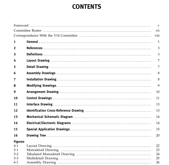
ASME Y14-24:2012 pdf download Types and Applications of Engineering Drawings Engineering Drawing and Related Documentation Practices
1.2.10 Unless Otherwise Specified (UOS). The phrase “unless otherwise specified” or the acronym “UOS” is used to indicate a default requirement. The phrase is used when default is a generally applied requirement and the exception can be clarified by providing a reference to another document or requirement.
1.3 Preparation Methods and Formats 1.3.1 Preparation Methods. Preparation methods (e.g., manual, digital, photographic, and cut and paste) and methods ofdepiction (e.g., pictorial, textual, or com- binations thereof) are concerns of this Standard only to the extent that the drawing satisfies its intended purpose. Use of ASME Y14.41 practices to prepare data sets does not preclude the use of this Standard. Data sets prepared with drawing graphic sheets shall meet the specific requirements for each drawing type defined in this Standard. Data sets prepared with no drawing 2 graphic sheets shall meet the intent of the specific requirements for each drawing type defined in this Standard byusingthe practicesdefined inASME Y14.41. 1.3.2 Formats. Formats (e.g., manual and digital, single or multisheet, drawing in book form, and com- puter printout) are concerns of this Standard only to the extent that the drawing satisfies its intended purpose. Formats shall be in accordance with ASME Y14.1.
1.4 Structure of Drawing Text Textual information on drawings may be in numbered note form or in a format that uses section headings, numbered paragraphs, and subparagraphs grouped according to subject matter. See figures for examples.
1.5 Application Guidelines Application guidelines are intended to aid in understanding the conditions under which specific types of drawings may be prepared. It is not intended that any application guideline imply that preparation of specific drawing types is always required.
1.6 Drawing Content Requirements may be satisfied by direct delineation on the drawing or by reference to other documents that are a part of the drawing package. Such documents are invoked in individual drawings either by reference in the general notes, in the using assembly parts list, or both. Parts lists shall be in accordance with ASME Y14.34.
1.7 Tabulation Any drawing type may be tabulated, as applicable, to delineate similar items that as a group have some common characteristics and some variable features.
1.7.1 Application Guidelines. Tabulated drawings are prepared to avoid preparation of individual draw- ings for each similar item tabulated. Each item included inthe tabulation shall have a PartorIdentifying Number (PIN) assigned.
1.7.2 Requirements. The differences, i.e., the vari- ables, between the items defined by the drawing are tabulated. The common characteristics are delineated or stated once. Each individual item is identified by a PIN. Normally, a single pictorial representation is shown. For example, variable dimensions are coded by letters used as headings for columns in a tabulation block. Variables are entered inthe table under the appro- priate heading and on the same line as the relevant PIN. Alternate methods may be used to correlate the variations in characteristics to the individual items. The description for each tabulated item is as complete as thatofanindividualitemdescribedonthespecificdraw- ing type.
1.8 Combination of Drawing Types The characteristics of more than one drawing type may be combined into a single drawing provided the resultingcombinationincludesthedatarequiredbyeach of the individual types. For example, a modification kit drawing combines a description of the modification and the kit of items needed to accomplish the modification.
NOTE: The decision to combine drawings should be made cau- tiously. Combining drawing types should result in a significant advantage versus not combining and having separate drawings. Advantages ofcombiningdrawings should outweighanypotential disadvantages. Potential disadvantages resulting from combining drawings include
(a) increased complexity of the drawing, which may diminish clarity and usefulness
(b) frequent change activity to the drawing, which may increase the need to update associated record(s), material control data, manufacturing planning, microfilm, etc.
1.9 Ancillary Drawings Ancillary drawings may be prepared to supplement end product drawings. Ancillary drawings may be required for management control, logistics purposes, configuration management, and other similar functions unique to a design activity. Ancillary drawings do not establish item identification. Inclusion of data in an ancillary drawing does noteliminate the need to prepare appropriate drawing types, including the applicable data as defined in this Standard. 1.10 Drawing Hierarchy Based onthe productstructure ofanitem, the different types of drawings required may be prepared at any level of the drawing tree. See section 16. 2 REFERENCES The following revisions of American National Standards form a part of this Standard to the extent specified herein. A more recent revision may be used, provided there is no conflict with this Standard. In the event of a conflict between this Standard and the refer- ences cited herein, this Standard shall take precedence.
ASME Y14-24:2012 pdf download
