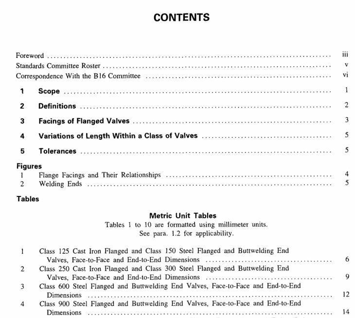
ASME B16.10:2000 pdf download FACE-T0-FACE AND END-TO-END DIMENSIONS OF VAIVES
ASME B16.47,Series A,or MsS SP-44.[For flangedend butterfly valves,refer to Note (3) of Table 8 (A8)for fange information.] For flangeless or wafer valvesintended for assembly between flanges,refer to Tables7and 8 (A7 and A8) for flange information. Onlybuttwelding end valves in rating Classes 150 through2500 are included in this Standard. Dimensional tablesfor various types and sizes of valves are as follows.1.5.1Gate,Globe,Angle.Check,Plug, andBall Valves
(a) Class 150 —Tables 1 and A1(b)Class 300 – Tables 2 and A2(c)Class 600 —Tables 3 and A3d) Class 900-— Tables 4 and A4(e) Class 1500— Tables 5 and A5Class 2500 —Tables 6 and A6
1.5.2 Y-Pattern Globe and Y-Pattern SwingCheck Valves
Class 150 – Tables 1 and Al
1.5.3 Wafer Knife Gate ValvesClass 15o — Tables 7 and A7
1.5.4 Wafer Swing Check ValvesClass 150 to 2500 — Tables 7 and A71.5.5 Butterfly Valves
a) Class 150 Tables 8 and A8(b) Class 300 _- Tables 8 and A8fc)Class 600 _- Tables 8 and A8
1.6 Convention
For the purpose of determining conformance .withthis Standard, the convention for fixing significant digitswhere limits,maximum or minimum values,are speci-fied shall be “rounding off’ as defined in ASTMPractice E29.This requires that an observed or calcu-lated value shall be rounded off to the nearest unit inthe last right-hand digit used for expressing the limit.Decimal values and tolerance do not imply a particularmethod of measurement.
2 DEFINITIONS
2.1 Valve Size Designation
2.1.1 (DN)(Nominal Diameter).The size of avalve is designated by the nominal size of its endconnections.This is denoted by (DN),a dimensionlessnumber indirectly related to the physical size of the connecting pipe (See Tables 1 through 10).The valvesize is not necessarily the same as the inside diameteror port diameter.
2.1.2 NPS (Nominal Pipe Size).The size of avalve is designated by the nominal size of its endconnections.This is denoted by NPS, a dimensionlessnumber indirectly related to the physical size of theconnecting pipe (See Tables A1’through A10). Thevalve size is not necessarily the same as the insidediameter or port diameter.
2.1.3 Reduced port, gate,and ball valves conformingto API 6D are designated for size by two numbers,the first being the NPS (DN) on the valve ends,thesecond being the NPS (DN) of the port (seats,movingparts, etc.); e.g., NPS 6×4(DN 150 x 100) designatesa valve of end size NPS 6 (DN 150) with a port tomatch NPS 4 (DN 100). These valves , shali haveface-to-face or end-to-end dimensions corresponding tovalves having the same size end connections; i.e.,aNPS 6 × 4(DN 150 x 100) valve shall have theface-to-face or end-to-end dimensions of a NPS 6 (DN150) valve.
2.1.4 Reduced port, pressure seal bonnet,gate, globe,and check valves are designated for size by threenumbers,the first and last being the NPS(DN) of thevalve ends,the second being the NPS (DN)of theport; e.g.,NPS 6 x4 × 6(DN 150 x 100 x 150)designates a valve having ends matching NPS 6(DN150y with a port to match NPS 4 (DN 1OO). Likewise,NPS 6 × 4 × 4 (DN150 × 100 x 100) woulddesignate a valve having one end matching NPS 6(DN 150),the other matching NPS 4 (DN 100),andthe port matching NPS 4 (DN100). These valves shallhave face-to-face or end-to-end dimensions correspond-ing to valves having the same port size; i.c.,either aNPS 6 × 4 × 6 (DN 150 x i00 x 150) or a NPS6×4 ×4 (DN 150 x 100 x 1o0) valve shall havethe face-to-face or end-to-end dimensions of a NPS 4(DN 100) valve.
2.2 Pressure Rating Designations
Valve class designations and related PNvalues aregiven below:
(a) Cast iron
2.3 Flanged Valve Dimensions
2.3.1 Face-to-Face.The face-to-face dimension forflanged valves is the distance between the extreme endswhich are the gasket contact surfaces (see Fig. 1). Face-to-face applies to flanged valves having the followingnominal flange facing identifiers:
(a) flat
(b) 2 mm (0.06 in.) raised(c) 7 mm (0.25 in.) raised(d) large or small male*(e) large or small tongue*
2.3.2 Installed Face-to-Face.The installed face-to-face dimension of certain butterfly valves [see Table8(A8),Note (1)] may include allowances for gasketor resilient-facing compression. Refer to MSS SP-67for definitive illustrations.
2.3.3 End-to-End. For those flanged valves wherethe gasket contact surfaces are not located at the extremeends of the valve,the distance between the extremeends is described as the end-to-end dimension andapplies to flanged valves having the following nominalflange facing identifiers:
(a) ring joint
(b) large or small female(c) large or small groove
ASME B16.10:2000 pdf download
